
Safety showers and eyewash: automating the weekly activation
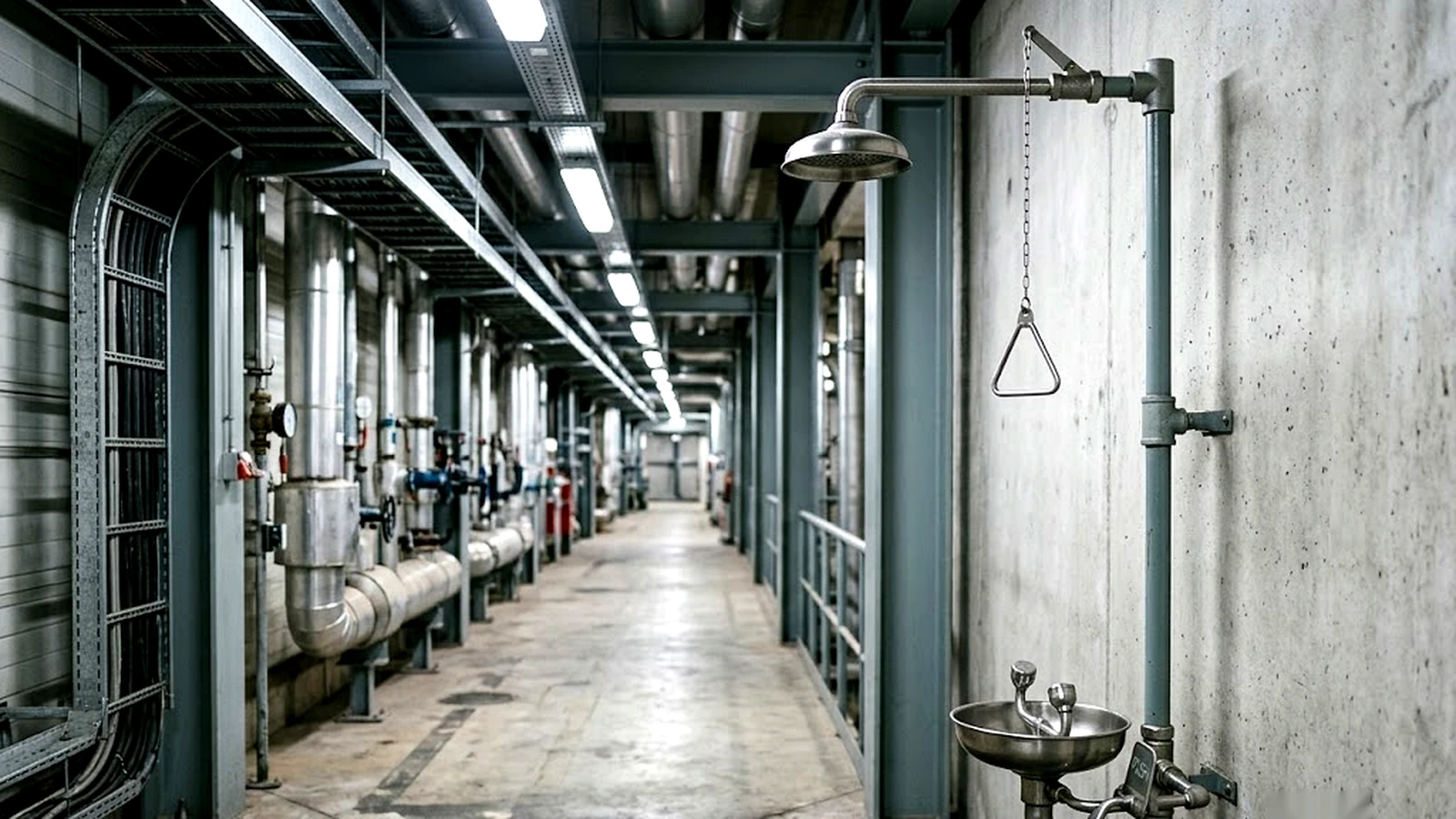
Plumbed emergency showers and eyewash stations are activated periodically to confirm they work and to move the water standing in their supply. Automation can take over the water side of that job at fixtures nobody visits often, but only if it is arranged so that no electronic failure can come between the user and the water. That constraint shapes the architecture and rules out the obvious approach.
- Z358.1 activation
- Weekly
- Plumbed units. Full inspection annually.
- Z358.1 delivery
- 15minutes
- From a valve that opens in about a second and stays open until deliberately closed.
- Bypass architecture
- No electronics in the emergency path
- A fault stops the flushing, not the shower.
In this section
What the standards ask for
Requirements differ by market in both content and legal force.
ANSI/ISEA Z358.1 is the reference standard, currently the 2014 edition reaffirmed in 2020. It is a voluntary consensus standard rather than law. Plumbed units are to be activated weekly, and there is a full inspection annually.
OSHA 29 CFR 1910.151(c) is the binding US requirement. It calls for suitable facilities for quick drenching or flushing where eyes or body may be exposed to injurious corrosive materials, and Z358.1 is the benchmark generally used to judge what counts as suitable.
The EN 15154 series covers this equipment by application, with separate parts for laboratory body showers, plumbed eye wash units, non-plumbed equipment, and body showers on sites other than laboratories. It is a performance and installation standard rather than law, adopted nationally and treated as best practice. It sets no single Europe-wide activation interval; testing frequency follows manufacturer instructions and national requirements.
AS 4775, Emergency eyewash and shower equipment, is an Australian Standard. AS 4775:2026 supersedes the 2007 edition. In New Zealand it is referred to widely in industry practice, but it is an Australian Standard rather than a joint AS/NZS document, and New Zealand guidance governs there.
Two of the Z358.1 provisions shape everything on this page. The weekly activation is short: long enough to confirm the unit operates and that flushing fluid is available at the head. It is not a performance test, and it is not the annual inspection. The equipment itself is intended to deliver flushing fluid for a full 15 minutes at a tepid temperature, from a valve that opens in about a second and stays open until it is deliberately closed.
Where these documents converge is in describing equipment that must deliver for a sustained period from a valve the user does not have to hold open. Where they diverge, and they do, is in activation frequency, inspection regime and delivery temperature, none of which transfer between markets.
One point on responsibility, since it decides how the rest of this page reads. A component’s capability does not by itself establish the conformity or compliance of the complete equipment and installation. That is settled at the level of the finished product and the site, not at the level of a control.
The activation does two jobs
The first is to confirm the fixture operates.
The second concerns the water. Between activations, water sits in the branch serving the fixture, and emergency equipment is by design almost never used, so that supply line is among the most reliably stagnant in a building. Where the supply is tempered, the upper part of the tepid range can favour microbial growth. A fixture that is mechanically sound can still discharge water that has been standing warm for weeks.
These two jobs come apart the moment you automate, and keeping them apart is the design problem.
Start from the failure analysis
A manual emergency shower is a hand valve on a live supply. Nothing electronic stands between the supply and the head.
Adding electronics to that path introduces failure modes that are mostly silent: a battery depleted since the last visit, a latching valve stuck or left part way, a failed coil or driver, a control fault. Routine checks can find some of them, but between checks they may remain undetected unless the system supervises itself and reports.
A single fault in the added system must not prevent water reaching the head. That principle survives every other question on this page.
Where a flush valve can go
On a manually actuated fixture the supply is live up to the hand valve, and everything beyond it is dry until someone opens it. An automated flush can therefore only draw water from upstream of that valve.
Single fault in the added system The flushing stops. The shower still works.
Single fault in the added system Can sit between the supply and the head. Only acceptable with a mechanical override, fail-available power and valve behaviour, and supervision.
A bypass leg
A tee upstream of the hand valve, a flush solenoid, and a line to drain. On its cycle the controller opens the solenoid and water runs from the live supply through the branch and out to drain. The flush path does not sit between the supply and the shower head, so a fault that prevents the bypass operating, such as a depleted battery or a valve stuck closed, stops the flushing while the shower still works. A bypass stuck open is a different case, and a hydraulic one.
This is one candidate architecture, not a default. It has to be engineered rather than assumed.
- Size the bypass so that a solenoid failing open cannot materially reduce the flow or pressure available to the fixture during a real activation.
- Provide isolation and backflow arrangements appropriate to the installation.
- Provide a drain that can take the discharge, which many emergency shower locations do not have.
- Decide how a stuck-open bypass is detected, since one discharging to a remote drain is not necessarily visible to anyone.
A valve in the supply path
This lets the cycle operate the fixture, which is what a full automated activation requires, and it only arises where the fixture is electronically actuated in the first place. Where it is chosen, the safety case has to be made explicitly: a mechanical override in parallel with the electronic actuation, a valve and power arrangement whose failure modes leave the supply available rather than isolated, supervision of battery state and valve position so faults are reported rather than discovered, and a defined response when the supervision itself is unavailable.
That is functional safety work, and a considerably larger scope than a timer driving a solenoid. Note also that where a standard requires the valve to stay open until deliberately closed, as Z358.1 does, no timed cut-off may sit in the emergency path.
What automation does and does not replace
Automated flushing on a bypass keeps the supply from standing between activations at fixtures nobody visits often. On sites with fixtures in remote corners, on unmanned installations, or at seasonal locations, that is where the water age problem sits.
It does not replace the periodic activation, which operates the fixture and checks that it works. It does not confirm that flushing fluid reached the head, that the spray pattern was correct, or that flow and temperature met the applicable requirement. Nor does it replace any inspection the applicable regime requires, which under Z358.1 is annual. Specify it as a water quality measure alongside the test regime, not as a way to reduce it.
For many sites the right answer remains a manual routine with a written record. Automated flushing earns its place where fixtures are numerous, remote, or seasonal, and where standing water is the dominant concern.
What a monitored fixture would require
Whether the activation itself can be automated and evidenced is a fair question, and the requirements are more demanding than a scheduled valve.
Such a system would measure delivery rather than assume it. Flow sensing gives direct evidence that fluid passed the point where it is measured, which is not the same as evidence that the spray pattern was correct or that the fixture performed as specified; pressure indicates that the line responded and is an inference rather than proof. It would record date, time, duration, and result per fixture, retrievable without a site visit. It would report its own battery state, valve position, and sensor health, since a monitoring function that fails silently gives false assurance. And it would have to satisfy a single-fault requirement: no failure of sensing, control, or power may impair emergency operation.
Visual checks and inspection would remain, because spray pattern, obstruction, and fixture condition are not measurable this way.
This is a development question rather than a component question.
Setting the cycle
The interval follows the site’s regime, commonly weekly where it accompanies the activation rhythm.
The duration should exchange the water held in the branch up to the tee. Calculate or estimate that volume, establish the flow through the bypass under representative conditions, divide, and add a margin. Where supply pressure varies across the day or the season, size on the minimum credible flow. On a tempered supply, establish which leg the cycle actually exchanges, since a blended arrangement may not fully exchange either the hot or the cold line.
In freezing climates, freeze protection shapes the architecture and the fixture selection, and any change to the flushing interval on that account needs a site-specific basis rather than a general rule. And the flush cycle should not run during a real activation, which is straightforward to arrange but has to be arranged deliberately.
Powering it where the fixture is
Emergency fixtures are often exactly where power is not. Where mains has to be run to each fixture, that work can be a significant part of the project cost, and on some sites it is what prevents automation being considered at all.
That makes the electronics a power budget problem. A controller waiting between weekly cycles spends nearly all its life idle, so standby current can dominate at this duty, while pulse energy, battery capacity and chemistry, temperature, and self-discharge all belong in the calculation. Valve choice follows: a latching solenoid draws current only during the pulses that open and close it, which is what makes a multi-year battery interval realistic.
On a bypass leg, a depleted battery is a maintenance failure rather than a safety one. That is the reason for keeping the battery there and not in the emergency path.
Records
A controller that reports events evidences that a cycle was commanded at a given time. That is a different kind of evidence from a manual record, not simply a better one: a controller record is generated reliably and cannot attest to anything beyond the command, while an observed manual activation can attest to discharge and to the condition of the fixture but depends on the person carrying it out.
Where an installation needs more, valve position shows the valve was driven or moved, pressure shows the line responded, and flow shows that water passed the point of measurement. None of them, on its own, evidences that the fixture performed as specified.
For most operators the useful outcome is a dated record per fixture showing that the flushing regime ran as configured, produced without anyone walking the site, and kept clearly separate from whatever activation and inspection records the applicable standard requires.
Working this into a product?
Tell us the application, the environment, and the power budget. We will come back with a configuration.
Request configured samplesNeed the control electronics behind it?
Programmable switching, sensing, and firmware, developed and manufactured in-house.
Discuss your product development