
Automatic flushing and water hygiene control: the engineering guide
Automatic flushing controls water age at selected outlets by opening the valve on a timer, so water standing in a low-use branch is replaced without anyone walking the building. It applies to outlets used rarely or not at all, and it works alongside temperature and disinfectant control rather than replacing them. The two settings that decide whether it works are the interval, taken from the site's regime, and the duration, derived from the branch volume and the flow actually available at the outlet.
- Growth range
- 20 to 45°C
- Growth is possible from roughly 20 degrees, with 25 to 45 the most favourable range.
- Typical interval
- 24 / 48 / 72h
- Common configurable settings. The interval follows a site assessment, not a general rule.
- Duration
- Volume ÷ flow
- Derived from the standing volume in the branch and the flow available at the outlet, plus a margin.
- Z358.1 activation
- Weekly
- Plumbed emergency showers and eyewash units in North America.
In this section
Water age
Water that stands still in a building changes. Any disinfectant residual present decays, temperature drifts toward the surrounding space, and the pipe wall gives biofilm a surface to establish on. Sediment and scale shelter organisms from whatever residual is left. Public health guidance generally treats these together: sediment and biofilm, temperature, water age, and disinfectant residual.
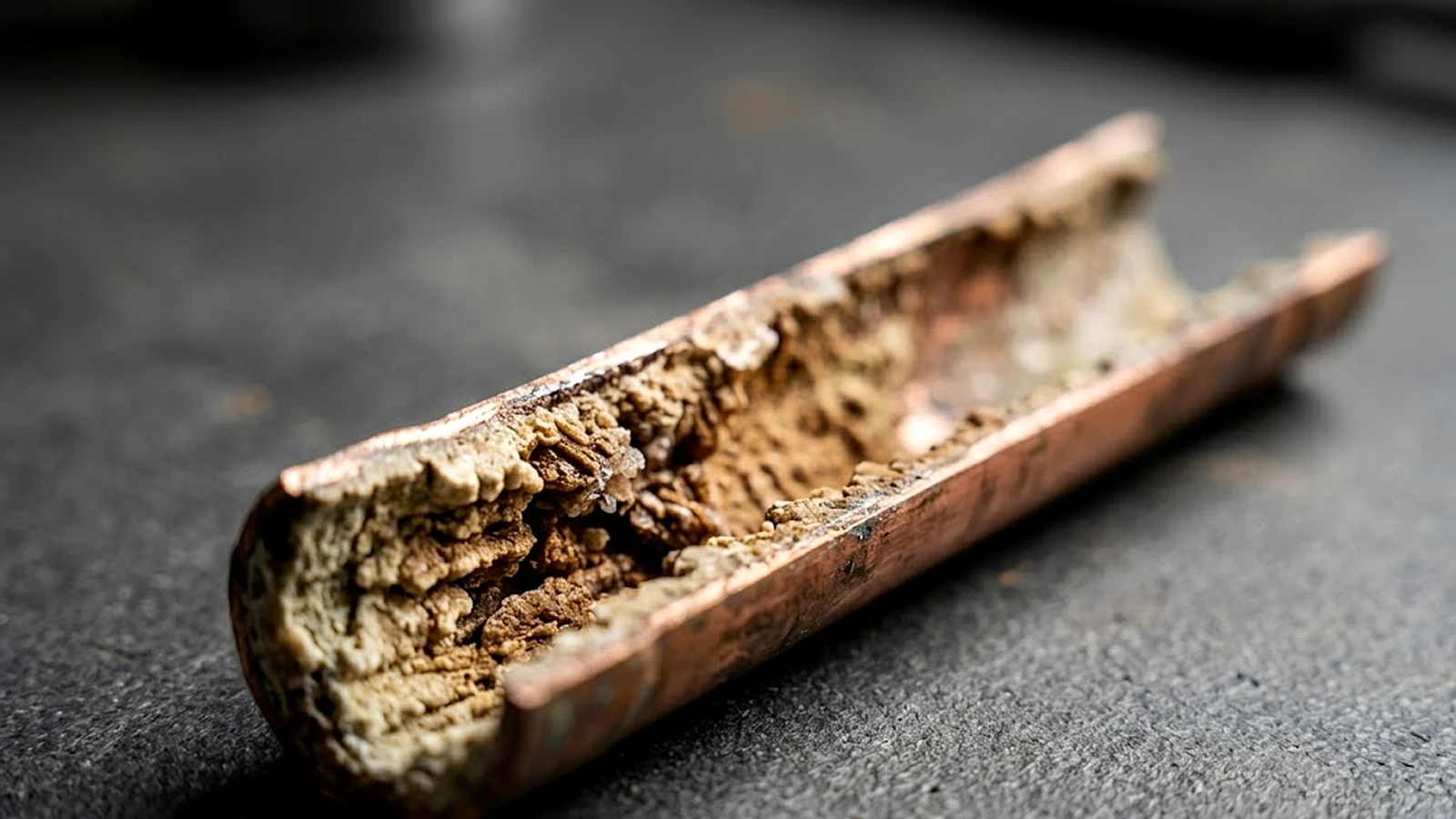
Water arriving from the supply is treated, but treated does not mean sterile. Low levels of organisms can be present, and what decides whether they matter is what the building does with the water afterwards: how long it holds it, at what temperature, with what residual, on what surface.
Legionella is the organism usually named, because it causes a serious pneumonia and because building water systems provide the conditions for its growth. Growth is possible from roughly 20 degrees Celsius, with the most favourable range generally given as 25 to 45 degrees, which describes cold water warmed by an unventilated riser and hot water that has cooled in a branch. The mechanism is not specific to that organism. Any system holding warm water still for long periods does the same thing.
So the problem is rarely that a building is unclean. It is that parts of it hold water for long periods, and those parts can usually be identified in advance.
Where water age concentrates
Stagnation is not spread evenly. It gathers in places the operator can usually name.
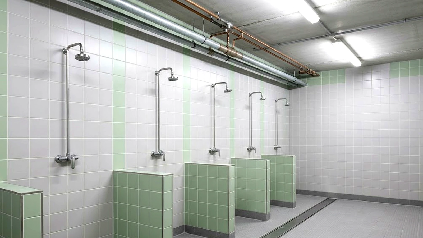
- Outlets used rarely. The unbooked guest room, the washroom in a quiet corridor, the shower in a facility busy two evenings a week, the second sink in a lab.
- Emergency fixtures. Safety showers and eyewash stations are, by design, almost never used, so their supply lines stand still between tests. This is one reason those tests exist.
- Whole areas during shutdown. Schools over the summer, seasonal accommodation, sports facilities between seasons, a floor closed for refurbishment.
- Systems running well below design flow. A building at half occupancy behaves hydraulically like a much emptier building, even where nothing is formally out of use.
Dead legs are a related but separate problem. Opening an outlet exchanges the water in the branch that hydraulically serves it. It does not purge a capped, isolated, or abandoned length of pipe that nothing draws through. Automatic flushing addresses low-use branches. True dead legs are a pipework question, usually resolved by removal or by rearranging the connection so water passes through.
The control measures, and where flushing sits
Building water hygiene rests on several control measures working together.
Keeps hot water above and cold water below the range where growth accelerates. It is a system-level design and operating job: storage temperature, circulation, insulation, balancing.
Maintains a residual through the system where the supply provides one, or introduces one as remediation.
Moves the water so age does not accumulate. Where an outlet is opened often enough, fresh water reaches the end of the branch and the standing volume is replaced.
All of them require ongoing operation, monitoring, and correction. None is set once and left. What distinguishes hydraulic control is that its execution depends on someone opening outlets, or on something doing it for them, at the locations identified as needing it. That dependency is what automation removes.
Manual regimes and how they fail
The manual version is a flushing schedule: staff visit each identified outlet, run it for a set time, and record what they did. It works while the routine holds, and the failure modes are worth naming, because they are what automation addresses.
| Dimension | Manual regime | Automatic regime |
|---|---|---|
| How it runs | Staff visit each identified outlet, run it for a set time, and record what they did. | A valve at the outlet, a controller that decides when to open it, and a power source. |
| Under pressure | The round competes with other tasks and gets shortened. | The cycle is a property of the configuration rather than of the staffing rota. |
| Holidays and handover | Schedules lapse when the person who owns the routine is absent, or when responsibility changes hands. | The schedule runs from the configured interval and, in smart mode, from the last activation. |
| Records | Kept by hand, and harder to reconstruct later. | Generated by the system. |
| Outlets used anyway | Without usage data, every outlet on the list gets the same treatment. | A smart cycle resets the timer whenever the outlet is used, so a flush follows a genuine idle period. |
| What it depends on | The routine behind it. | A functioning valve, a correct branch calculation, and a flow that still matches commissioning. |
Neither column is free of dependencies. Automation moves the dependency from the staffing rota to the configuration and the hydraulic calculation.
A manual regime is also blunt in a way that costs water. Without usage data, whoever walks the route cannot tell which outlets were used yesterday and which have stood since spring.
None of this makes manual flushing wrong. Plenty of sites run it well. It does mean the regime is only as reliable as the routine behind it.
What an automatic flush does
An automatic flush needs a valve at the outlet, a controller that decides when to open it, and a power source. Four settings describe most regimes in use.
How long the outlet may stand unused before a flush runs. Twenty four, forty eight, and seventy two hours are common configurable settings, and weekly appears on emergency fixtures where a maintenance activation is scheduled alongside the required test. There is no single accepted flushing frequency across buildings and jurisdictions, and guidance is explicit that the interval should follow a site assessment rather than a general rule.
How long the valve stays open. This is where regimes are most often set badly, because the number tends to be guessed. It can be derived instead, from the standing volume in the branch and the flow actually available at the outlet.
A standard cycle runs on its interval regardless of use. A smart cycle resets the timer whenever the outlet is used, so a flush follows a genuine idle period. Smart mode avoids cycles at outlets that were used anyway, which reduces consumption; how much depends on when activations fall relative to the cycle rather than on how many there are. Standard cycles remain useful where the site’s programme specifies a fixed interval that must run irrespective of use, and where every outlet should be identically configured and simple to describe.
A one-time offset after power-up, so the schedule does not begin at the hour of commissioning. Commission at two in the afternoon with a twelve hour delay and the first cycle falls at two in the morning. What the delay sets is the starting point of the schedule, not a fixed time of day: the clock time only holds where the cycle is a whole number of days and the unit stays powered, and in smart mode later use moves the next flush relative to the last activation.
Deriving the duration
Calculate or estimate the volume held in the branch between the outlet and the point where water is moving. Establish the flow at the outlet under conditions representative of normal operation, at commissioning or by measurement. Where supply pressure varies materially across the day or the season, size the duration on the minimum credible flow, or control the pressure. Then divide volume by flow and add a margin.
A duration below that will exchange or dilute part of the standing volume, but it will not achieve the full replacement the regime is designed for. A duration well above it mostly adds water consumption, and where the discharged water is heated or tempered it adds energy cost as well; the hygiene benefit falls away once the standing volume has been exchanged.
On a mixed outlet, establish which supply path the cycle actually exchanges, since a blended flush may not fully exchange either the hot or the cold line.
Once volume and flow are established, the controller repeats the timed opening. Permanent flow measurement is not required for the regime to be valid.
Set the interval from the site’s programme, derive the duration, confirm the hydraulic path, and the regime becomes a property of the configuration rather than of the staffing rota. That assumes a functioning valve, a correct branch calculation, and a flow that still matches commissioning.
Architectures
Three arrangements cover most installations, and they are stages rather than alternatives.
Standalone. The controller at the outlet holds its parameters and runs them with no connection to anything. It suits retrofits, sites without mains power, and buildings with no central system to report to. Its limitation is that it cannot tell anyone what it did.
Locally readable. The same device, with a service connection that lets a technician read status and events on site and change parameters without replacing hardware.
Connected. Outlet devices report into a central system, so events and status become central data. How they report varies with the installation: a dry contact or a digital output into a local controller, an analogue signal, a serial connection, a field bus, or native building protocols, sometimes through a gateway and sometimes not. Connection reduces visits made purely to read or record what a controller did. It does not replace physical inspection, water quality sampling, or the verification steps a water management programme requires, and it adds cabling, commissioning, and configuration work of its own.
Where reporting is likely to be required later, it is worth checking at selection whether a device can move from standalone to connected without being replaced. Where it plainly will not be, that capability is cost without purpose.
Records, and what they prove
Preventing water from standing and being able to show that you prevented it are two requirements, and some water management programmes ask for the second in writing.
Be precise about what each arrangement evidences. A manual regime evidences a logbook. A standalone controller evidences its configuration, plus the reasonable inference that it ran as configured. A controller that reports events evidences that a command was issued and recorded at a given time, which is stronger, but a command record is not a record of electrical output, valve movement, or water flow. Each of those needs its own evidence: an output or valve position signal shows the valve was driven or moved, a pressure signal shows the line responded, and a flow measurement shows water actually passed. Those cost more, and only some installations justify them.
The regulations, in outline
These documents are not equivalent in force, and it is worth keeping the categories apart. Some are law, some are voluntary consensus standards that become binding only where an authority, insurer, or contract adopts them, some are recognised technical rules, and some are public health guidance.
Directive (EU) 2020/2184 sets the frame for member states, which were required to transpose it by January 2023. It requires risk assessment of domestic distribution systems, with Legionella measures targeting at least priority premises such as hospitals, care homes and hotels. National regimes sit beneath it and differ considerably in how far they go.
In Germany, the Trinkwasserverordnung is an ordinance with legal force and places duties on system operators. The DVGW W 551 series are technical rules describing recognised practice for operation and stagnation rather than law in themselves. See TrinkwV und DVGW W 551.
In the Netherlands, the Drinkwaterbesluit goes further than most. Owners of priority installations, a category including hospitals and care homes, hotels, campsites, swimming pools and prisons, must hold a risk analysis and a written management plan prepared by a firm certified under BRL 6010, keep a logbook of the measures taken, and have the water sampled at least twice a year.
In the United Kingdom, outside the EU regime since Brexit, the framework is the HSE Approved Code of Practice L8 with the guidance in HSG274, and HTM 04-01 in healthcare premises.
ANSI/ISEA Z358.1 is a voluntary consensus standard, and the usual reference for emergency showers and eyewash equipment. It calls for plumbed units to be activated weekly, which both checks the equipment and moves the water standing in the supply. See safety showers and eyewash: automating the Z358.1 weekly activation.
OSHA 29 CFR 1910.141 is a US federal regulation, binding on covered employers. It requires workplace washing facilities to be maintained in a sanitary condition. It does not establish a general flushing or stagnation record requirement.
ASHRAE 188 and ASHRAE 514 are consensus standards describing water management as a programme: identify where risk sits, set control measures and limits, monitor, and confirm the programme works. Flushing regimes and their records sit inside that structure. Some authorities and accreditation bodies require such a programme.
CDC and Health Canada publish guidance rather than binding rules, covering low-use outlets, reopening after low occupancy, and the practical detail of a programme.
AS/NZS 3666, Air-handling and water systems of buildings, microbial control, is the reference standard for Legionella control in building water systems, covering design and installation, operation and maintenance, and performance-based monitoring. It is given force through state public health legislation, so registration, risk management plan and sampling requirements differ between states. Warm water systems delivering through outlets where aerosols may be generated fall within its scope. AS 4775 covers emergency eyewash and shower equipment separately. Both are Australian Standards, and New Zealand guidance governs there.
These documents specify outcomes, duties, and in places control limits and verification steps. Within those constraints, the method is generally left to the designer.
A specification path
For a facility engineer, the sequence is short.
- Identify the outlets at risk and the hydraulic branches that actually serve them.
- Choose the interval from the site’s water management programme and the applicable guidance.
- Calculate the standing volume in each branch.
- Establish the flow at the outlet under representative conditions, allowing for pressure variation.
- Set duration from volume and flow, with a margin.
- Confirm which path the cycle exchanges on mixed outlets.
- Decide what evidence the site needs, and choose the architecture that produces it.
Building it
For a manufacturer of sanitary or safety products, these requirements arrive as a development scope rather than a specification.
Scheduled flushing needs a controller with a real-time element, parameters that can be set per outlet, and defined behaviour when a user presses during a cycle or power is interrupted mid-flush.
Where the fixture has no mains supply, the design becomes a power budget: standby current, the energy each valve actuation costs, the duty profile, and a service life calculated from measured figures rather than estimated.
Wet and washdown environments constrain the switching, the sealing and the materials, and every choice among them carries a trade. Sealed mechanical switching brings moving parts and wear. Solid state removes that wear path and moves the problem into electronics design and sensitivity tuning. Optical sensing avoids contact and introduces its own dependencies.
Reporting into a building system can mean anything from a dry contact to a native protocol, and the choice shapes the electronics as much as the software.
And because requirements change across a product’s life, the control logic has to be revisable, whether for later production runs or for a specific customer programme.
That combination is a platform, and it is a different engineering discipline from valves, fixtures and enclosures. Inside electronic water management systems describes what such a platform contains. Developing flushing electronics in-house or sourcing them sets out the decision.
Working this into a product?
Tell us the application, the environment, and the power budget. We will come back with a configuration.
Request configured samplesNeed the control electronics behind it?
Programmable switching, sensing, and firmware, developed and manufactured in-house.
Discuss your product development