
Connecting flushing control to building management systems
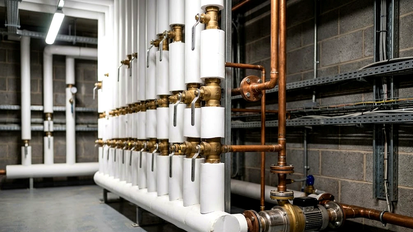
Connecting outlet-level flushing control to a building system makes a regime that runs quietly into one that can be supervised and adjusted centrally. The connection can be as simple as a contact closure into a local controller, or a field bus reaching building protocols through a gateway. The constraint that shapes most designs is power, because on a battery every hour a communication interface spends listening is energy the device does not have.
In this section
Why connect at all
One reason is evidence. A building with several hundred controlled outlets has several hundred small records, and central collection is the difference between an operator answering a question about one outlet on one date in seconds, and someone walking a site with a torch.
Beyond that, connection turns discovery into notification. A battery approaching end of life, or a cycle that did not run, is worth knowing when it happens rather than at the next inspection. What can be alarmed depends entirely on what the device reports: a contact closure evidences only that a signal was issued, and a serial connection carries only the parameters and events its register or point map implements.
It also removes the stepladder from routine changes. Adjusting an interval across a wing, staggering cycles so a whole riser does not flush at once, or switching a regime when occupancy changes, all done from the same place the rest of the plant is managed.
The non-reason is that connection does not make the regime more correct. A networked system with a badly chosen duration will exchange too little water, or waste it, at every outlet it controls.
Get the hydraulic settings right first.
What is actually exchanged
The data set is small.
Cycle and activation events with timestamps, current parameters, device status, and where the hardware supports it, temperature at the outlet or feedback confirming the valve moved.
Parameter changes, a command to run a cycle now, a clock reference, and where relevant an instruction to suspend cycles during maintenance.
That is a handful of registers or objects per outlet. The engineering effort is not in the payload. It sits in addressing and commissioning, and in the power budget wherever devices run on batteries.
The protocol landscape
Buildings are not greenfield, and the protocol at the top of the stack is usually decided before anyone specifies a tap.
BACnet is a widely used building automation protocol at the supervisory layer, particularly in commercial and institutional estates, and is a common target for anything that needs to appear alongside HVAC and energy systems.
Modbus is a common option at device and controller level. Implementations are widely available on both sides of the link, in outlet devices and in the controllers and gateways that collect from them, which is what makes it a practical way to get outlet-level data as far as something that speaks the building protocol.
KNX is used mainly for room and building automation, including lighting, blinds, and room control, and appears in commercial buildings and hotels as well as residential ones. In water applications, KNX material concentrates on leak detection, metering, flow monitoring, and shut-off rather than on scheduled hygiene flushing. Treat it as a secondary integration target where a project already uses KNX for room automation, reached through a gateway or a local controller, rather than as an outlet-level protocol.
Metering and low-power wireless protocols appear at the edge, particularly where devices are battery powered and cabling is impractical.
Two practical points follow. An outlet controller rarely needs to speak the supervisory protocol itself; it needs to reach something that does. And protocol choice is usually inherited from the building, so a product with a straightforward device-level interface and a gateway path will fit more projects than one that commits to a single supervisory protocol.
How devices connect
Four arrangements are common.
The controller drives an output when a cycle runs, and a local controller, PLC, or input module counts and timestamps it. Little to configure and little to go wrong. It carries no parameters, no device status, and no diagnosis.
The device sits on a bus with others and answers to an address, giving access to whatever parameters and events its map implements. Applicable where cabling exists or can be run in a riser.
Outlet devices report to a small controller serving a zone, which aggregates and speaks the building protocol upstream. Keeps the outlet devices simple and puts the complexity in one place per zone.
Where cabling is the obstacle, which is often the same situation in which the device is battery powered. Radio is usually handled by a module rather than integrated into the outlet controller, which keeps the choice of wireless technology open.
Power shapes the architecture
This is the constraint that separates a specification that works from one that disappoints.
A mains-powered outlet device can keep an interface active, answer promptly, and behave like any other field device. On a battery, availability and latency are bought with energy, and the design has to decide how much of each it wants. Low-power networks handle that trade in different ways: scheduled receive windows at agreed times, periodic polling initiated by the device, or a low-duty persistent connection where the radio and protocol permit it.
The consequences for a specification are practical rather than exotic. Immediate response to an unscheduled query may not be available. Commands may be queued centrally and collected by the device at its next window. Clock handling has to account for the device not being continuously synchronised. And the reporting interval itself becomes an energy decision, not a preference: reporting every event promptly costs more than batching.
None of that rules out connected battery devices. It does mean that a design which assumes continuous polling behaviour will not deliver the service life the specification asked for. Where reporting is not genuinely needed, keeping battery devices standalone remains a legitimate answer.
Commissioning is the real work
Integrating one outlet is a bounded task with a known method, and the interface documentation tells you most of what you need. Across several hundred, the same work becomes a project, because the effort moves from the interface to the identity and configuration of every device.
- Give every device an address and a location identity that means something to the operator, so an alarm reads as a room and a fixture rather than a node number.
- Set parameters per outlet, since branch volumes differ even where the site works from a small number of standard regime profiles.
- Coordinate cycle timing across the building: offset to spread demand, or grouped where the regime or the hydraulic design calls for a target flow velocity in shared pipework.
- Build and test the mapping between device points and building system objects once per point type, then replicate.
Security, briefly
Outlet controllers sit on networks alongside more sensitive systems, and that adjacency is the point.
Keep the field layer segmented from general IT, do not expose gateways directly to the internet, change default credentials, and treat remote parameter access as a privileged function rather than a convenience. Where a system offers cloud access, be clear about what leaves the building and who can reach it. Treat an unsegmented device as a potential route to something else, and design accordingly.
What a good integration looks like
Judged in operation rather than at commissioning, a good integration is unremarkable. Cycles appear as events against named outlets. Conditions the device can actually detect raise alarms with enough context to dispatch someone. Parameters can be read back, so the record shows what the device was set to rather than what a drawing says. And it degrades sensibly: when the network is unavailable the outlet devices keep running their regimes, because the regime belongs to the device and not to the network.
Connection should add supervision to a system that already works without it.
Working this into a product?
Tell us the application, the environment, and the power budget. We will come back with a configuration.
Request configured samplesNeed the control electronics behind it?
Programmable switching, sensing, and firmware, developed and manufactured in-house.
Discuss your product development